BHPian Jeroen recently shared this with other enthusiasts.
We have some excellent threads on the forum about airconditioning, notably car AC systems, obviously! Car air conditioning compressor
I have worked on the AC systems of my Jeep Cherokee and my wife Ford Fiesta during the last 12 months or so. All detailled in my thread of fiddling with my cars. At the end of this post I will provide links to each repair job.
Recently my friendly AC specialist and neighbour Jack and I replaced the AC compressor on the Fiesta. I thought it would be interesting to open it up and get a feel for what is inside. According to my mum I started taking things apart from when I was about 3 years old. Initially, I did have problems putting stuff back together again. Apparently I took our central heating furnace apart when my parents were not looking. They only noticed when it was getting cold in the sitting room, and they had to call in a specialist to put it back together again. These days I do manage a bit better. Usually I manage to put things back together.
I also wanted to take this compressor apart to see if, over time, I can make it into one of these ‘cut-away’ display thingies. Would look pretty cool in my garage!!
So buckle up and lets rip this compressor apart!! It is going to get a bit technical, if not nerdy. Mostly all mechanical so I hope most folks can follow!
I am not going to explain in detail how an AC system works. Just a brief very general explanation. Have a look at this diagram
The compressor, compresses (Duh!) the refrigerant and pushes it through the evaporator. The evaporator is usually mounted behind your dashboard and tends to be part of the cabinet air circulation system. (see my Jeep jobs as I will mention later).
The evaporator cools down the refrigerant, because the downstream expansion valve controls the flow, based on the temperature upstream. The refrigerant is piped though a dryer (to take out any moisture) and ends up in the condensor (usually at the front of your car, behind or in front of the radiator).
In essence that is all, in reality it is a bit more complex, but not by much. I don’t want to go into to much details/physics.
Here is a good explanation on how your car AC system works, showing some more detail.
Of course, these days on our modern cars the AC is controlled through various systems and has multiple sensor providing input (internal- external temperature, sunload (that little plastic blob on your dashboard close to the window!), various system pressures and temperatures.
This is the functional diagram of the Ford Fiesta AC system. The same has been used since about 2012. It is probably a little more advanced now.
There are a number of different compressors out there. The main difference tends to be whether they have a clutch system or variable or a combination of both.
Clutch only, you will find on older systems/cars (E.g. my Jeep and Alfa Romeo Spider). Combined clutch/variable is the most common variant these days. And the Fiesta has one of these.
On a clutch only system the compressor clutch is activated based on the low pressure part of the system. it is an ON/OFF system. It’s fully on, or not. On most cars you will hear a very distinct “click” when the clutch engages. Depending on the system and the circumstance, your clutch will cycle on and off all the time, usually with an interval of 20-60 seconds or so.
We will see in more detail how the variable compressor works. You will see that a variable compressor will run continuously, but the volume of refrigerant it pumps is controlled. The problem with this approach is that your variable compressor runs as soon as the engine starts, even if you are not using the AC. It will cause wear and it draws a little power from the engine as well of course. (negative impact on fuel efficiency)
Also, some of the variable compressor did not last long when they were not used. As you will see, if they run without pumping the lubrication can become a problem. Especially if you begin to run low on refrigerant. (The refrigerant holds and circulates the oil as well!
So that is why these days we tend to see clutch-variable compressors.
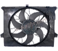
Here you see the old and the new compressor. Guess which one we installed in the Fiesta and which one we’ll be taking apart!
The big black pulley at the front also houses the clutch, you see an electrical lead with connector protruding. This is to activate the magnet that pulls the clutch in.
On the bottom you see another black connector mounted on top of the compressor housing. It is actually on top of the control valve of the variable displacement mechanism as we will see.
It is important to know whether your new compressor has already oil in it or not. Each AC system takes a very precise amount of lubrication oil. So if the compressor is already filled, you need to add less. When filling, or rather recharging as it is known, the system, you add refrigerant with the correct quantity of lubrication oil and a dye. The dye allows for easy leak detection.
In your car workshop manual it will mention how much oil needs to go in the system and also how much oil each main component will hold. (e.g. the compressor, the dryer, the evaporator etc.) So if you replace one component you have some idea on how much oil to replace as well
Always good to check the type/model plate of your compressor. As you can see this is an original Ford Motor Company compressor. It was made in Hungary in 2015 and it takes R134A refrigerant. R134A is more or less the default type of refrigerant these days.
A closer look of the clutch at the front of the pulley:
Here you see that electrical lead going into the electromagnet.
In order to take the pulley and the clutch off, that little bolt on the shaft needs to come off. Only way to hold the pulley was to put it in my vise and use a small socket to undo the little nut.
Here you see the inside of the clutch pate. When activated the electromagnet pulls it towards the pulley. So the clutch plate goes directly on the pulley! Notice the bearing in the centre of the pulley. Without the clutch being engaged, the pulley just free wheels and the compressor is standing idle, whereas the pulley still spins, driven by a V-belt, similar to your alternator.
Notice that the clutch plate centre piece has splines on it, that fit on corresponding spines on the compressor shaft. So the clutch is attached directly to the compressor shaft, the pulley freewheel on the shaft, until the clutch engages.
The clutch plate seen from above. It is the actual clutch plate with a spring attached to a smaller plate. The electromagnet pulls the clutch plate and when it disengages the springs pulls it off the pulley. Only a few mm. The gap is a good indication of the wear of the clutch. On my Jeep I replaced the bearing and on an earlier Jeep I had to replace the whole clutch too as it was worn out. To thin and the electromagnet won’t be able to pull it against the pulley tightly anymore.
Here you see from right to left as I have taken everything off; The little bolt and washer that holds everything together, the clutch plate, a circlip that locks up the bearing on the pulley, the pulley with the bearing still inside. the rest of the compressor with on the right hand side the now exposed electro magnet.
If anything wears out on these compressors it tends to be the bearing and or clutch. Bear in mind, when you don’t use the compressor the pulley is still running, so it is still wearing. Of all the AC jobs I have done over the years, bearing comes first, clutch comes second. (apart from filling the AC system). Luckily, replacing the clutch and or the bearing is fairly easy on most compressors. It rarely requires taking the compressor out of the car and thus no need to extract the refrigerant charge first. Check the links at the end of this post for the AC clutch bearing replacement I did on my Jeep.
A close up of that electro magnet. Notice the green felt. It provides what I believe is a seal against dirt and grime coming from the clutch. The clutch drive protrusion fits in here and is sealed, sort of by the felt
Same sequence as above, but now I have taken the electro magnet off as well. It is held in place with a circlip as well. Notice the green dye on the sprocket of the clutch? A tell tale of the leak!!!
Here we are looking toward the front assembly of the compressor. So everything we took off comes from this side. One thing you will notice is all this green gunk. That is actually lubrication oil and dye!
So this where the Fiesta system developed a leak. A compressor will most likely leak in one of three places. Either the inlet or output pipe. This is usually an easy fix, you pull the pipe off, replacing the O-ring and that is usually it. However, the third option tends to be the most frequent one, a front seal leak of the compressor shaft itself. That is what happens here. That is how we determined this was the problem. We looked for the dye (with UV light it is even more visible) and around the front of the compressor was the only place where we could spot the dye.
Notice the splines on the shaft. Now look at the images of the clutch plate, it has corresponding splines. So the clutch plate fits on top of the compressor shaft. There is a direct connection between the clutch and the compressor shaft. When disengaged the pulley freewheel freely (?) around the shaft. When the clutch engages, it locks up the (rotating) pulley against the compressor which is still standing still. Thus the compressor shaft starts to rotate.
You will notice another bearing and circlip deep inside that recess at the front of the compressor. In theory you should be able to replace all of those. In practice, as you will see that is quite a complex and tricky job, requiring some special tooling. That’s why in the west everybody replaces a compressor with a leaking front seal. First of all, you are likely not to be able to get these individual parts very easily. Car manufacturers often use different compressors, so there is also a variety of spare parts out there. In addition, labour is expensive in the west. You also run the risk of replacing the seal, recharging the system and having to redo everything again if it is still leaking. So replacing is often the easiest and cheapest solution.
These front seals do not wear out quickly. Actually, Jack told me that it was pretty unusual to see problems with the Ford AC compressors. Trust our bad luck. Our Fiesta is a 2015 and has done about 97K.
That bearing/top of the seal has a special sort of felt piece around it. I am not 100% sure of its function, but I suspect to keep dirt and grime away from the bearing and the front seal. Just for extra protection. Would love to hear from somebody in the know.
With another circlip undone, we can start pulling the compressor body apart. There are three distinct different parts to it. I have pulled off one part. The middle part which has the cilinders in it is still attached to the rear which contains the control solenoid and some clever valve plates
Continue reading BHPian Jeroen's thread on car AC compressors for more insights and information.
TRSE09 compressor Keep yourself tuned in to the Indian automotive scene via Twitter, Youtube or RSS feeds.